What are "series" and "parallel" circuits?
1.)Circuits consisting of just one battery and one load resistance are very simple to analyze, but they are not often found in practical applications. Usually, we find circuits where more than two components are connected together.
There are two basic ways in which to connect more than two circuit components: series and parallel. First, an example of a series circuit:
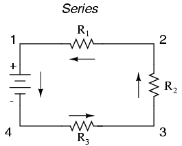
Here, we have three resistors (labeled R1, R2, and R3), connected in a long chain from one terminal of the battery to the other. (It should be noted that the subscript labeling -- those little numbers to the lower-right of the letter "R" -- are unrelated to the resistor values in ohms. They serve only to identify one resistor from another.) The defining characteristic of a series circuit is that there is only one path for electrons to flow. In this circuit the electrons flow in a counter-clockwise direction, from point 4 to point 3 to point 2 to point 1 and back around to 4.
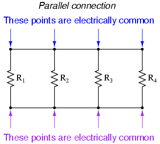
Now, let's look at the other type of circuit, a parallel configuration:
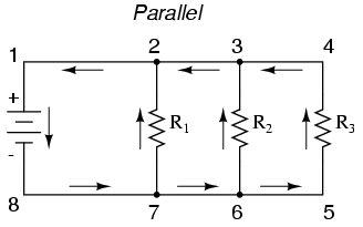
Again, we have three resistors, but this time they form more than one continuous path for electrons to flow. There's one path from 8 to 7 to 2 to 1 and back to 8 again. There's another from 8 to 7 to 6 to 3 to 2 to 1 and back to 8 again. And then there's a third path from 8 to 7 to 6 to 5 to 4 to 3 to 2 to 1 and back to 8 again. Each individual path (through R1, R2, and R3) is called a branch.
The defining characteristic of a parallel circuit is that all components are connected between the same set of electrically common points. Looking at the schematic diagram, we see that points 1, 2, 3, and 4 are all electrically common. So are points 8, 7, 6, and 5. Note that all resistors as well as the battery are connected between these two sets of points.
And, of course, the complexity doesn't stop at simple series and parallel either! We can have circuits that are a combination of series and parallel, too:
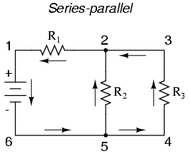
In this circuit, we have two loops for electrons to flow through: one from 6 to 5 to 2 to 1 and back to 6 again, and another from 6 to 5 to 4 to 3 to 2 to 1 and back to 6 again. Notice how both current paths go through R1 (from point 2 to point 1). In this configuration, we'd say that R2 and R3 are in parallel with each other, while R1 is in series with the parallel combination of R2 and R3.
This is just a preview of things to come. Don't worry! We'll explore all these circuit configurations in detail, one at a time!
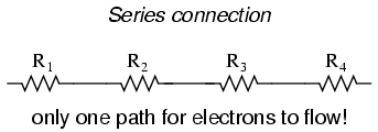
The basic idea of a "series" connection is that components are connected end-to-end in a line to form a single path for electrons to flow:
The basic idea of a "parallel" connection, on the other hand, is that all components are connected across each other's leads. In a purely parallel circuit, there are never more than two sets of electrically common points, no matter how many components are connected. There are many paths for electrons to flow, but only one voltage across all components:
Series and parallel resistor configurations have very different electrical properties. We'll explore the properties of each configuration in the sections to come.
example:
equivalent resistance of resistors in series : R = R1 + R2 + R3 + ...

With a 10 V battery, by V = I R the total current in the circuit is:
I = V / R = 10 / 20 = 0.5 A. The current through each resistor would be 0.5 A.
Parallel circuits
A parallel circuit is a circuit in which the resistors are arranged with their heads connected together, and their tails connected together. The current in a parallel circuit breaks up, with some flowing along each parallel branch and re-combining when the branches meet again. The voltage across each resistor in parallel is the same.The total resistance of a set of resistors in parallel is found by adding up the reciprocals of the resistance values, and then taking the reciprocal of the total:
equivalent resistance of resistors in parallel: 1 / R = 1 / R1 + 1 / R2 + 1 / R3 +...
With a 10 V battery, by V = I R the total current in the circuit is: I = V / R = 10 / 2 = 5 A.
The individual currents can also be found using I = V / R. The voltage across each resistor is 10 V, so:
I1 = 10 / 8 = 1.25 A
I2 = 10 / 8 = 1.25 A
I3=10 / 4 = 2.5 A
Note that the currents add together to 5A, the total current.
A parallel resistor short-cut
If the resistors in parallel are identical, it can be very easy to work out the equivalent resistance. In this case the equivalent resistance of N identical resistors is the resistance of one resistor divided by N, the number of resistors. So, two 40-ohm resistors in parallel are equivalent to one 20-ohm resistor; five 50-ohm resistors in parallel are equivalent to one 10-ohm resistor, etc.When calculating the equivalent resistance of a set of parallel resistors, people often forget to flip the 1/R upside down, putting 1/5 of an ohm instead of 5 ohms, for instance. Here's a way to check your answer. If you have two or more resistors in parallel, look for the one with the smallest resistance. The equivalent resistance will always be between the smallest resistance divided by the number of resistors, and the smallest resistance. Here's an example.
You have three resistors in parallel, with values 6 ohms, 9 ohms, and 18 ohms. The smallest resistance is 6 ohms, so the equivalent resistance must be between 2 ohms and 6 ohms (2 = 6 /3, where 3 is the number of resistors).
Doing the calculation gives 1/6 + 1/12 + 1/18 = 6/18. Flipping this upside down gives 18/6 = 3 ohms, which is certainly between 2 and 6.
Circuits with series and parallel components
Many circuits have a combination of series and parallel resistors. Generally, the total resistance in a circuit like this is found by reducing the different series and parallel combinations step-by-step to end up with a single equivalent resistance for the circuit. This allows the current to be determined easily. The current flowing through each resistor can then be found by undoing the reduction process.General rules for doing the reduction process include:
- Two (or more) resistors with their heads directly connected together and their tails directly connected together are in parallel, and they can be reduced to one resistor using the equivalent resistance equation for resistors in parallel.
- Two resistors connected together so that the tail of one is connected to the head of the next, with no other path for the current to take along the line connecting them, are in series and can be reduced to one equivalent resistor.
Learnings mike?
ReplyDelete