Thévenin's theorem
From Wikipedia, the free encyclopedia

Any black box containing resistances only and voltage and current sources can be replaced to a Thévenin equivalent circuit consisting of an equivalent voltage source in series connection with an equivalent resistance.
- Any linear electrical network with voltage and current sources and only resistances can be replaced at terminals A-B by an equivalent voltage source Vth in series connection with an equivalent resistance Rth.
- This equivalent voltage Vth is the voltage obtained at terminals A-B of the network with terminals A-B open circuited.
- This equivalent resistance Rth is the resistance obtained at terminals A-B of the network with all its independent current sources open circuited and all its independent voltage sources short circuited.
The theorem also applies to frequency domain AC circuits consisting of reactive and resistive impedances.
The theorem was independently derived in 1853 by the German scientist Hermann von Helmholtz and in 1883 by Léon Charles Thévenin (1857–1926), an electrical engineer with France's national Postes et Télégraphes telecommunications organization.
Thévenin's theorem and its dual, Norton's theorem, are widely used for circuit analysis simplification and to study circuit's initial-condition and steady-state response. Thévenin's theorem can be used to convert any circuit's sources and impedances to a Thévenin equivalent; use of the theorem may in some cases be more convenient than use of Kirchhoff's circuit laws.
Calculating the Thévenin equivalent
To calculate the equivalent circuit, the resistance and voltage are needed, so two equations are required. These two equations are usually obtained by using the following steps, but any conditions placed on the terminals of the circuit should also work:- Calculate the output voltage, VAB, when in open circuit condition (no load resistor—meaning infinite resistance). This is VTh.
- Calculate the output current, IAB, when the output terminals are short circuited (load resistance is 0). RTh equals VTh divided by this IAB.
Step 2 could also be thought of as:
- 2a. Replace the independent voltage sources with short circuits, and independent current sources with open circuits.
- 2b. Calculate the resistance between terminals A and B. This is RTh.
The Thévenin-equivalent resistance is the resistance measured across points A and B "looking back" into the circuit. It is important to first replace all voltage- and current-sources with their internal resistances. For an ideal voltage source, this means replace the voltage source with a short circuit. For an ideal current source, this means replace the current source with an open circuit. Resistance can then be calculated across the terminals using the formulae for series and parallel circuits. This method is valid only for circuits with independent sources. If there are dependent sources in the circuit, another method must be used such as connecting a test source across A and B and calculating the voltage across or current through the test source.
Example

Step 0: The original circuit
|

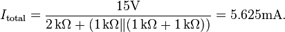
Step 1: Calculating the equivalent output voltage
|

Step 2: Calculating the equivalent resistance
|

Step 3: The equivalent circuit
|


Calculating equivalent resistance:
![R_\mathrm{Th} = R_1 + \left[ \left( R_2 + R_3 \right) \| R_4 \right]](http://upload.wikimedia.org/math/7/3/a/73a3d9cdd44d9b5c884560a8b0b64da3.png)
![= 1\,\mathrm{k}\Omega + \left[ \left( 1\,\mathrm{k}\Omega + 1\,\mathrm{k}\Omega \right) \| 2\,\mathrm{k}\Omega \right]](http://upload.wikimedia.org/math/e/4/4/e449fecf600a8678ded70fcd120543bf.png)
Norton's theorem
From Wikipedia, the free encyclopediaThis article is about the theorem in electrical circuits. For Norton's theorem for queueing networks, see flow-equivalent server method.Known in Europe as the Mayer–Norton theorem, Norton's theorem holds, to illustrate in DC circuit theory terms, that (see image):
-
- Any linear electrical network with voltage and current sources and only resistances can be replaced at terminals A-B by an equivalent current source INO in parallel connection with an equivalent resistance RNO.
- This equivalent current INO is the current obtained at terminals A-B of the network with terminals A-B short circuited.
- This equivalent resistance RNO is the resistance obtained at terminals A-B of the network with all its voltage sources short circuited and all its current sources open circuited.
The Norton equivalent circuit is used to represent any network of linear sources and impedances at a given frequency.
Norton's theorem and its dual, Thévenin's theorem, are widely used for circuit analysis simplification and to study circuit's initial-condition and steady-state response. Any black box containing resistances only and voltage and current sources can be replaced by an equivalent circuit consisting of an equivalent current source in parallel connection with an equivalent resistance.
Norton's theorem was independently derived in 1926 by Siemens & Halske researcher Hans Ferdinand Mayer (1895–1980) and Bell Labs engineer Edward Lawry Norton (1898–1983).[1][2][3][4][5]
To find the equivalent,
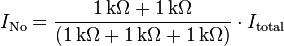
- Find the Norton current INo. Calculate the output current, IAB, with a short circuit as the load (meaning 0 resistance between A and B). This is INo.
- Find the Norton resistance RNo. When there are no dependent sources (all current and voltage sources are independent), there are two methods of determining the Norton impedance RNo.
-
-
- Calculate the output voltage, VAB, when in open circuit condition (i.e., no load resistor – meaning infinite load resistance). RNo equals this VAB divided by INo.
- or
- Replace independent voltage sources with short circuits and independent current sources with open circuits. The total resistance across the output port is the Norton impedance RNo.
-

- However, when there are dependent sources, the more general method must be used. This method is not shown below in the diagrams.
-
- Connect a constant current source at the output terminals of the circuit with a value of 1 Ampere and calculate the voltage at its terminals. This voltage divided by the 1 A current is the Norton impedance RNo. This method must be used if the circuit contains dependent sources, but it can be used in all cases even when there are no dependent sources.
-
Contents
Example of a Norton equivalent circuit
|
Step 0: The original circuit
|

Step 1: Calculating the equivalent output current
|
Step 2: Calculating the equivalent resistance
|

Step 3:design the equivalent circuit
|


Conversion to a Thévenin equivalent


No comments:
Post a Comment