Maximum power transfer theorem
From Wikipedia, the free encyclopedia
In electrical engineering, the maximum power transfer theorem states that, to obtain maximum external power from a source with a finite internal resistance, the resistance of the load must equal the resistance of the source as viewed from its output terminals. Moritz von Jacobi published the maximum power (transfer) theorem around 1840; it is also referred to as "Jacobi's law".[1]The theorem results in maximum power transfer, and not maximum efficiency. If the resistance of the load is made larger than the resistance of the source, then efficiency is higher, since a higher percentage of the source power is transferred to the load, but the magnitude of the load power is lower since the total circuit resistance goes up.
If the load resistance is smaller than the source resistance, then most of the power ends up being dissipated in the source, and although the total power dissipated is higher, due to a lower total resistance, it turns out that the amount dissipated in the load is reduced.
The theorem states how to choose (so as to maximize power transfer) the load resistance, once the source resistance is given. It is a common misconception to apply the theorem in the opposite scenario. It does not say how to choose the source resistance for a given load resistance. In fact, the source resistance that maximizes power transfer is always zero, regardless of the value of the load resistance.
The theorem can be extended to alternating current circuits that include reactance, and states that maximum power transfer occurs when the load impedance is equal to the complex conjugate of the source impedance.
Maximizing power transfer versus power efficiency
The theorem was originally misunderstood (notably by Joule) to imply that a system consisting of an electric motor driven by a battery could not be more than 50% efficient since, when the impedances were matched, the power lost as heat in the battery would always be equal to the power delivered to the motor. In 1880 this assumption was shown to be false by either Edison or his colleague Francis Robbins Upton, who realized that maximum efficiency was not the same as maximum power transfer. To achieve maximum efficiency, the resistance of the source (whether a battery or a dynamo) could be made close to zero. Using this new understanding, they obtained an efficiency of about 90%, and proved that the electric motor was a practical alternative to the heat engine.

The condition of maximum power transfer does not result in maximum efficiency. If we define the efficiency
 as the ratio of power dissipated by the load to power developed by the
source, then it is straightforward to calculate from the above circuit
diagram that
as the ratio of power dissipated by the load to power developed by the
source, then it is straightforward to calculate from the above circuit
diagram that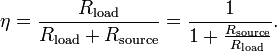
- If
 , then
- If
 or
or  then
then 
- If
 , then
Impedance matching
Main article: impedance matching
A related concept is reflectionless impedance matching. In radio, transmission lines, and other electronics, there is often a requirement to match the source impedance (such as a transmitter) to the load impedance (such as an antenna) to avoid reflections in the transmission line.Calculus-based proof for purely resistive circuits
(See Cartwright[2] for a non-calculus-based proof)
 and fixed source resistance
  , to a load with resistance
  , resulting in a current
  . By Ohm's law, is simply the source voltage divided by the total circuit resistance:
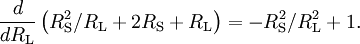
 dissipated in the load is the square of the current multiplied by the resistance:
 for which this expression is a maximum could be calculated by differentiating it, but it is easier to calculate the value of for which the denominator
 :
:

 and
are both positive, so the positive sign in the above is the correct
solution. To find out whether this solution is a minimum or a maximum,
the denominator expression is differentiated again:
and
are both positive, so the positive sign in the above is the correct
solution. To find out whether this solution is a minimum or a maximum,
the denominator expression is differentiated again: and , showing that the denominator is a minimum, and the power is therefore a maximum, when
In reactive circuits
The theorem also applies where the source and/or load are not totally resistive. This invokes a refinement of the maximum power theorem, which says that any reactive components of source and load should be of equal magnitude but opposite phase. (See below for a derivation.) This means that the source and load impedances should be complex conjugates of each other. In the case of purely resistive circuits, the two concepts are identical. However, physically realizable sources and loads are not usually totally resistive, having some inductive or capacitive components, and so practical applications of this theorem, under the name of complex conjugate impedance matching, do, in fact, exist.If the source is totally inductive (capacitive), then a totally capacitive (inductive) load, in the absence of resistive losses, would receive 100% of the energy from the source but send it back after a quarter cycle. The resultant circuit is nothing other than a resonant LC circuit in which the energy continues to oscillate to and fro. This is called reactive power. Power factor correction (where an inductive reactance is used to "balance out" a capacitive one), is essentially the same idea as complex conjugate impedance matching although it is done for entirely different reasons.
For a fixed reactive source, the maximum power theorem maximizes the real power (P) delivered to the load by complex conjugate matching the load to the source.
For a fixed reactive load, power factor correction minimizes the apparent power (S) (and unnecessary current) conducted by the transmission lines, while maintaining the same amount of real power transfer. This is done by adding a reactance to the load to balance out the load's own reactance, changing the reactive load impedance into a resistive load impedance.
Proof

 (peak voltage) and fixed source impedance
  , to a load with impedance
  , resulting in a phasor magnitude current
  . is simply the source voltage divided by the total circuit impedance:
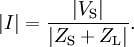
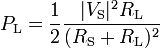
 dissipated in the load is the square of the current multiplied by the resistive portion (the real part)
  of the load impedance:
 and reactance
  are the real and imaginary parts of , and
  is the imaginary part of .
To determine the values of
and (since  , , and are fixed) for which this expression is a maximum, we first find, for each fixed positive value of , the value of the reactive term for which the denominator

 which maximizes this expression. However, this maximization problem has
exactly the same form as in the purely resistive case, and the
maximizing condition
which maximizes this expression. However, this maximization problem has
exactly the same form as in the purely resistive case, and the
maximizing condition  can be found in the same way.
The combination of conditions


A capacitor (originally known as a condenser) is a passive two-terminal electrical component used to store energy electrostatically in an electric field. The forms of practical capacitors vary widely, but all contain at least two electrical conductors (plates) separated by a dielectric (i.e. insulator). The conductors can be thin films, foils or sintered beads of metal or conductive electrolyte, etc. The "nonconducting" dielectric acts to increase the capacitor's charge capacity. A dielectric can be glass, ceramic, plastic film, air, vacuum, paper, mica, oxide layer etc. Capacitors are widely used as parts of electrical circuits in many common electrical devices. Unlike a resistor, an ideal capacitor does not dissipate energy. Instead, a capacitor stores energy in the form of an electrostatic field between its plates.
When there is a potential difference across the conductors (e.g., when a capacitor is attached across a battery), an electric field develops across the dielectric, causing positive charge +Q to collect on one plate and negative charge −Q to collect on the other plate. If a battery has been attached to a capacitor for a sufficient amount of time, no current can flow through the capacitor. However, if a time-varying voltage is applied across the leads of the capacitor, a displacement current can flow.
An ideal capacitor is characterized by a single constant value for its capacitance. Capacitance is expressed as the ratio of the electric charge Q on each conductor to the potential difference V between them. The SI unit of capacitance is the farad (F), which is equal to one coulomb per volt (1 C/V). Typical capacitance values range from about 1 pF (10−12 F) to about 1 mF (10−3 F).
The capacitance is greater when there is a narrower separation between conductors and when the conductors have a larger surface area. In practice, the dielectric between the plates passes a small amount of leakage current and also has an electric field strength limit, known as the breakdown voltage. The conductors and leads introduce an undesired inductance and resistance.
Capacitors are widely used in electronic circuits for blocking direct current while allowing alternating current to pass. In analog filter networks, they smooth the output of power supplies. In resonant circuits they tune radios to particular frequencies. In electric power transmission systems, they stabilize voltage and power flow.[1]


Daniel Gralath was the first to combine several jars in parallel into a "battery" to increase the charge storage capacity. Benjamin Franklin investigated the Leyden jar and came to the conclusion that the charge was stored on the glass, not in the water as others had assumed. He also adopted the term "battery",[5][6] (denoting the increasing of power with a row of similar units as in a battery of cannon), subsequently applied to clusters of electrochemical cells.[7] Leyden jars were later made by coating the inside and outside of jars with metal foil, leaving a space at the mouth to prevent arcing between the foils.[citation needed] The earliest unit of capacitance was the jar, equivalent to about 1.11 nanofarads.[8]
Leyden jars or more powerful devices employing flat glass plates alternating with foil conductors were used exclusively up until about 1900, when the invention of wireless (radio) created a demand for standard capacitors, and the steady move to higher frequencies required capacitors with lower inductance. More compact construction methods began to be used, such as a flexible dielectric sheet (like oiled paper) sandwiched between sheets of metal foil, rolled or folded into a small package.
Early capacitors were also known as condensers, a term that is still occasionally used today, particularly in high power applications, like automotive systems. The term was first used for this purpose by Alessandro Volta in 1782, with reference to the device's ability to store a higher density of electric charge than a normal isolated conductor.[9]
Theory of operation
Main article: Capacitance
Overview

Charge separation in a parallel-plate capacitor causes an internal
electric field. A dielectric (orange) reduces the field and increases
the capacitance.

A simple demonstration of a parallel-plate capacitor
An ideal capacitor is wholly characterized by a constant capacitance C, defined as the ratio of charge ±Q on each conductor to the voltage V between them:[10]

Sometimes charge build-up affects the capacitor mechanically, causing its capacitance to vary. In this case, capacitance is defined in terms of incremental changes:

Hydraulic analogy

In the hydraulic analogy,
a capacitor is analogous to a rubber membrane sealed inside a pipe.
This animation illustrates a membrane being repeatedly stretched and
un-stretched by the flow of water, which is analogous to a capacitor
being repeatedly charged and discharged by the flow of charge.
- The current alters the charge on a capacitor, just as the flow of water changes the position of the membrane. More specifically, the effect of an electric current is to increase the charge of one plate of the capacitor, and decrease the charge of the other plate by an equal amount. This is just as when water flow moves the rubber membrane, it increases the amount of water on one side of the membrane, and decreases the amount of water on the other side.
- The more a capacitor is charged, the larger its voltage drop; i.e., the more it "pushes back" against the charging current. This is analogous to the fact that the more a membrane is stretched, the more it pushes back on the water.
- Charge can flow "through" a capacitor even though no individual electron can get from one side to the other. This is analogous to the fact that water can flow through the pipe even though no water molecule can pass through the rubber membrane. Of course, the flow cannot continue in the same direction forever; the capacitor will experience dielectric breakdown, and analogously the membrane will eventually break.
- The capacitance describes how much charge can be stored on one plate of a capacitor for a given "push" (voltage drop). A very stretchy, flexible membrane corresponds to a higher capacitance than a stiff membrane.
- A charged-up capacitor is storing potential energy, analogously to a stretched membrane.
Energy of electric field
Work must be done by an external influence to "move" charge between the conductors in a capacitor. When the external influence is removed, the charge separation persists in the electric field and energy is stored to be released when the charge is allowed to return to its equilibrium position. The work done in establishing the electric field, and hence the amount of energy stored, is[13]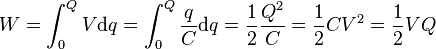
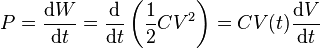
In the case of a fluctuating voltage V(t), the stored energy also fluctuates and hence power must flow into or out of the capacitor. This power can be found by taking the time derivative of the stored energy:
Current–voltage relation
The current I(t) through any component in an electric circuit is defined as the rate of flow of a charge Q(t) passing through it, but actual charges—electrons—cannot pass through the dielectric layer of a capacitor. Rather, one electron accumulates on the negative plate for each one that leaves the positive plate, resulting in an electron depletion and consequent positive charge on one electrode that is equal and opposite to the accumulated negative charge on the other. Thus the charge on the electrodes is equal to the integral of the current as well as proportional to the voltage, as discussed above. As with any antiderivative, a constant of integration is added to represent the initial voltage V(t0). This is the integral form of the capacitor equation:[14]

DC circuits
See also: RC circuit

A simple resistor-capacitor circuit demonstrates charging of a capacitor.

AC circuits
See also: reactance (electronics) and electrical impedance § Deriving the device-specific impedances
Impedance, the vector sum of reactance and resistance,
describes the phase difference and the ratio of amplitudes between
sinusoidally varying voltage and sinusoidally varying current at a given
frequency. Fourier analysis allows any signal to be constructed from a spectrum
of frequencies, whence the circuit's reaction to the various
frequencies may be found. The reactance and impedance of a capacitor are
respectively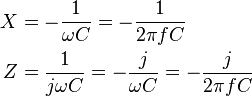
Impedance decreases with increasing capacitance and increasing frequency. This implies that a higher-frequency signal or a larger capacitor results in a lower voltage amplitude per current amplitude—an AC "short circuit" or AC coupling. Conversely, for very low frequencies, the reactance will be high, so that a capacitor is nearly an open circuit in AC analysis—those frequencies have been "filtered out".
Capacitors are different from resistors and inductors in that the impedance is inversely proportional to the defining characteristic; i.e., capacitance.
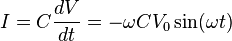
A capacitor connected to a sinusoidal voltage source will cause a displacement current to flow through it. In the case that the voltage source is V0cos(ωt), the displacement current can be expressed as:
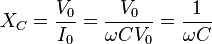
XC approaches zero as ω approaches infinity. If XC approaches 0, the capacitor resembles a short wire that strongly passes current at high frequencies. XC approaches infinity as ω approaches zero. If XC approaches infinity, the capacitor resembles an open circuit that poorly passes low frequencies.
The current of the capacitor may be expressed in the form of cosines to better compare with the voltage of the source:

Laplace circuit analysis (s-domain)
When using the Laplace transform in circuit analysis, the impedance of an ideal capacitor with no initial charge is represented in the s domain by:
- C is the capacitance, and
- s is the complex frequency.
Parallel-plate model

Dielectric is placed between two conducting plates, each of area A and with a separation of d
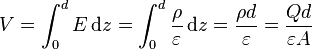

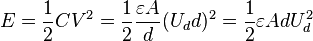
A parallel plate capacitor can only store a finite amount of energy before dielectric breakdown occurs. The capacitor's dielectric material has a dielectric strength Ud which sets the capacitor's breakdown voltage at V = Vbd = Udd. The maximum energy that the capacitor can store is therefore

Several capacitors in parallel
Networks
See also: Series and parallel circuits
- For capacitors in parallel
- Capacitors in a parallel configuration each have the same applied voltage. Their capacitances add up. Charge is apportioned among them by size. Using the schematic diagram to visualize parallel plates, it is apparent that each capacitor contributes to the total surface area.

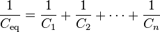
- For capacitors in series

Several capacitors in series
- Connected in series, the schematic diagram reveals that the separation distance, not the plate area, adds up. The capacitors each store instantaneous charge build-up equal to that of every other capacitor in the series. The total voltage difference from end to end is apportioned to each capacitor according to the inverse of its capacitance. The entire series acts as a capacitor smaller than any of its components.
- Capacitors are combined in series to achieve a higher working voltage, for example for smoothing a high voltage power supply. The voltage ratings, which are based on plate separation, add up, if capacitance and leakage currents for each capacitor are identical. In such an application, on occasion, series strings are connected in parallel, forming a matrix. The goal is to maximize the energy storage of the network without overloading any capacitor. For high-energy storage with capacitors in series, some safety considerations must be applied to ensure one capacitor failing and leaking current will not apply too much voltage to the other series capacitors.
- Series connection is also sometimes used to adapt polarized electrolytic capacitors for bipolar AC use. See electrolytic capacitor#Designing for reverse bias.
- Voltage distribution in parallel-to-series networks.
- To model the distribution of voltages from a single charged capacitor
 connected in parallel to a chain of capacitors in series
  :
:
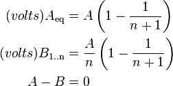
- Note: This is only correct if all capacitance values are equal.
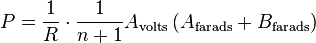
- The power transferred in this arrangement is:
Non-ideal behavior
Capacitors deviate from the ideal capacitor equation in a number of ways. Some of these, such as leakage current and parasitic effects are linear, or can be assumed to be linear, and can be dealt with by adding virtual components to the equivalent circuit of the capacitor. The usual methods of network analysis can then be applied. In other cases, such as with breakdown voltage, the effect is non-linear and normal (i.e., linear) network analysis cannot be used, the effect must be dealt with separately. There is yet another group, which may be linear but invalidate the assumption in the analysis that capacitance is a constant. Such an example is temperature dependence. Finally, combined parasitic effects such as inherent inductance, resistance, or dielectric losses can exhibit non-uniform behavior at variable frequencies of operation.Breakdown voltage
Main article: Breakdown voltage
Above a particular electric field, known as the dielectric strength Eds,
the dielectric in a capacitor becomes conductive. The voltage at which
this occurs is called the breakdown voltage of the device, and is given
by the product of the dielectric strength and the separation between the
conductors,[18]
For air dielectric capacitors the breakdown field strength is of the order 2 to 5 MV/m; for mica the breakdown is 100 to 300 MV/m; for oil, 15 to 25 MV/m; it can be much less when other materials are used for the dielectric.[20] The dielectric is used in very thin layers and so absolute breakdown voltage of capacitors is limited. Typical ratings for capacitors used for general electronics applications range from a few volts to 1 kV. As the voltage increases, the dielectric must be thicker, making high-voltage capacitors larger per capacitance than those rated for lower voltages. The breakdown voltage is critically affected by factors such as the geometry of the capacitor conductive parts; sharp edges or points increase the electric field strength at that point and can lead to a local breakdown. Once this starts to happen, the breakdown quickly tracks through the dielectric until it reaches the opposite plate, leaving carbon behind and causing a short (or relatively low resistance) circuit. The results can be explosive as the short in the capacitor draws current from the surrounding circuitry and dissipates the energy.[21]
The usual breakdown route is that the field strength becomes large enough to pull electrons in the dielectric from their atoms thus causing conduction. Other scenarios are possible, such as impurities in the dielectric, and, if the dielectric is of a crystalline nature, imperfections in the crystal structure can result in an avalanche breakdown as seen in semi-conductor devices. Breakdown voltage is also affected by pressure, humidity and temperature.[22]
Equivalent circuit

Two different circuit models of a real capacitor

Similarly to ESR, the capacitor's leads add equivalent series inductance or ESL to the component. This is usually significant only at relatively high frequencies. As inductive reactance is positive and increases with frequency, above a certain frequency capacitance will be canceled by inductance. High-frequency engineering involves accounting for the inductance of all connections and components.
If the conductors are separated by a material with a small conductivity rather than a perfect dielectric, then a small leakage current flows directly between them. The capacitor therefore has a finite parallel resistance,[12] and slowly discharges over time (time may vary greatly depending on the capacitor material and quality).
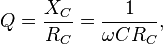
Q factor
The quality factor (or Q) of a capacitor is the ratio of its reactance to its resistance at a given frequency, and is a measure of its efficiency. The higher the Q factor of the capacitor, the closer it approaches the behavior of an ideal, lossless, capacitor.The Q factor of a capacitor can be found through the following formula:
 is angular frequency,
  is the capacitance,
  is the capacitive reactance, and
  is the series resistance of the capacitor.
Ripple current
Ripple current is the AC component of an applied source (often a switched-mode power supply) whose frequency may be constant or varying. Ripple current causes heat to be generated within the capacitor due to the dielectric losses caused by the changing field strength together with the current flow across the slightly resistive supply lines or the electrolyte in the capacitor. The equivalent series resistance (ESR) is the amount of internal series resistance one would add to a perfect capacitor to model this. Some types of capacitors, primarily tantalum and aluminum electrolytic capacitors, as well as some film capacitors have a specified rating value for maximum ripple current.- Tantalum electrolytic capacitors with solid manganese dioxide electrolyte are limited by ripple current and generally have the highest ESR ratings in the capacitor family. Exceeding their ripple limits can lead to shorts and burning parts.
- Aluminum electrolytic capacitors, the most common type of electrolytic, suffer a shortening of life expectancy at higher ripple currents. If ripple current exceeds the rated value of the capacitor, it tends to result in explosive failure.
- Ceramic capacitors generally have no ripple current limitation and have some of the lowest ESR ratings.
- Film capacitors have very low ESR ratings but exceeding rated ripple current may cause degradation failures.
Capacitance instability
The capacitance of certain capacitors decreases as the component ages. In ceramic capacitors, this is caused by degradation of the dielectric. The type of dielectric, ambient operating and storage temperatures are the most significant aging factors, while the operating voltage has a smaller effect. The aging process may be reversed by heating the component above the Curie point. Aging is fastest near the beginning of life of the component, and the device stabilizes over time.[23] Electrolytic capacitors age as the electrolyte evaporates. In contrast with ceramic capacitors, this occurs towards the end of life of the component.Temperature dependence of capacitance is usually expressed in parts per million (ppm) per °C. It can usually be taken as a broadly linear function but can be noticeably non-linear at the temperature extremes. The temperature coefficient can be either positive or negative, sometimes even amongst different samples of the same type. In other words, the spread in the range of temperature coefficients can encompass zero. See the data sheet in the leakage current section above for an example.
Capacitors, especially ceramic capacitors, and older designs such as paper capacitors, can absorb sound waves resulting in a microphonic effect. Vibration moves the plates, causing the capacitance to vary, in turn inducing AC current. Some dielectrics also generate piezoelectricity. The resulting interference is especially problematic in audio applications, potentially causing feedback or unintended recording. In the reverse microphonic effect, the varying electric field between the capacitor plates exerts a physical force, moving them as a speaker. This can generate audible sound, but drains energy and stresses the dielectric and the electrolyte, if any.
Current and voltage reversal
Current reversal occurs when the current changes direction. Voltage reversal is the change of polarity in a circuit. Reversal is generally described as the percentage of the maximum rated voltage that reverses polarity. In DC circuits, this will usually be less than 100% (often in the range of 0 to 90%), whereas AC circuits experience 100% reversal.In DC circuits and pulsed circuits, current and voltage reversal are affected by the damping of the system. Voltage reversal is encountered in RLC circuits that are under-damped. The current and voltage reverse direction, forming a harmonic oscillator between the inductance and capacitance. The current and voltage will tend to oscillate and may reverse direction several times, with each peak being lower than the previous, until the system reaches an equilibrium. This is often referred to as ringing. In comparison, critically damped or over-damped systems usually do not experience a voltage reversal. Reversal is also encountered in AC circuits, where the peak current will be equal in each direction.
For maximum life, capacitors usually need to be able to handle the maximum amount of reversal that a system will experience. An AC circuit will experience 100% voltage reversal, while under-damped DC circuits will experience less than 100%. Reversal creates excess electric fields in the dielectric, causes excess heating of both the dielectric and the conductors, and can dramatically shorten the life expectancy of the capacitor. Reversal ratings will often affect the design considerations for the capacitor, from the choice of dielectric materials and voltage ratings to the types of internal connections used.[24]
Dielectric absorption
Capacitors made with some types of dielectric material show "dielectric absorption" or "soakage". On discharging a capacitor and disconnecting it, after a short time it may develop a voltage due to hysteresis in the dielectric. This effect can be objectionable in applications such as precision sample and hold circuits.Leakage
Leakage is equivalent to a resistor in parallel with the capacitor. Constant exposure to heat can cause dielectric breakdown and excessive leakage, a problem often seen in older vacuum tube circuits, particularly where oiled paper and foil capacitors were used. In many vacuum tube circuits, interstage coupling capacitors are used to conduct a varying signal from the plate of one tube to the grid circuit of the next stage. A leaky capacitor can cause the grid circuit voltage to be raised from its normal bias setting, causing excessive current or signal distortion in the downstream tube. In power amplifiers this can cause the plates to glow red, or current limiting resistors to overheat, even fail. Similar considerations apply to component fabricated solid-state (transistor) amplifiers, but owing to lower heat production and the use of modern polyester dielectric barriers this once-common problem has become relatively rare.Electrolytic failure from disuse
Electrolytic capacitors are conditioned when manufactured by applying a voltage sufficient to initiate the proper internal chemical state. This state is maintained by regular use of the equipment. If a system using electrolytic capacitors is unused for a long period of time it can lose its conditioning, and will generally fail with a short circuit when next operated, permanently damaging the capacitor. To prevent this in tube equipment, the voltage can be slowly brought up using a variable transformer (variac) on the mains, over a twenty or thirty minute interval. Transistor equipment is more problematic as such equipment may be sensitive to low voltage ("brownout") conditions, with excessive currents due to improper bias in some circuits.[citation needed]Capacitor types
Main article: Types of capacitor
Practical capacitors are available commercially in many different
forms. The type of internal dielectric, the structure of the plates and
the device packaging all strongly affect the characteristics of the
capacitor, and its applications.Values available range from very low (picofarad range; while arbitrarily low values are in principle possible, stray (parasitic) capacitance in any circuit is the limiting factor) to about 5 kF supercapacitors.
Above approximately 1 microfarad electrolytic capacitors are usually used because of their small size and low cost compared with other types, unless their relatively poor stability, life and polarised nature make them unsuitable. Very high capacity supercapacitors use a porous carbon-based electrode material.
Dielectric materials

Capacitor materials. From left: multilayer ceramic, ceramic disc,
multilayer polyester film, tubular ceramic, polystyrene, metalized
polyester film, aluminum electrolytic. Major scale divisions are in
centimetres.
In order to maximise the charge that a capacitor can hold, the dielectric material needs to have as high a permittivity as possible, while also having as high a breakdown voltage as possible.
Several solid dielectrics are available, including paper, plastic, glass, mica and ceramic materials. Paper was used extensively in older devices and offers relatively high voltage performance. However, it is susceptible to water absorption, and has been largely replaced by plastic film capacitors. Plastics offer better stability and ageing performance, which makes them useful in timer circuits, although they may be limited to low operating temperatures and frequencies. Ceramic capacitors are generally small, cheap and useful for high frequency applications, although their capacitance varies strongly with voltage and they age poorly. They are broadly categorized as class 1 dielectrics, which have predictable variation of capacitance with temperature or class 2 dielectrics, which can operate at higher voltage. Glass and mica capacitors are extremely reliable, stable and tolerant to high temperatures and voltages, but are too expensive for most mainstream applications. Electrolytic capacitors and supercapacitors are used to store small and larger amounts of energy, respectively, ceramic capacitors are often used in resonators, and parasitic capacitance occurs in circuits wherever the simple conductor-insulator-conductor structure is formed unintentionally by the configuration of the circuit layout.
Electrolytic capacitors use an aluminum or tantalum plate with an oxide dielectric layer. The second electrode is a liquid electrolyte, connected to the circuit by another foil plate. Electrolytic capacitors offer very high capacitance but suffer from poor tolerances, high instability, gradual loss of capacitance especially when subjected to heat, and high leakage current. Poor quality capacitors may leak electrolyte, which is harmful to printed circuit boards. The conductivity of the electrolyte drops at low temperatures, which increases equivalent series resistance. While widely used for power-supply conditioning, poor high-frequency characteristics make them unsuitable for many applications. Electrolytic capacitors will self-degrade if unused for a period (around a year), and when full power is applied may short circuit, permanently damaging the capacitor and usually blowing a fuse or causing failure of rectifier diodes (for instance, in older equipment, arcing in rectifier tubes). They can be restored before use (and damage) by gradually applying the operating voltage, often done on antique vacuum tube equipment over a period of 30 minutes by using a variable transformer to supply AC power. Unfortunately, the use of this technique may be less satisfactory for some solid state equipment, which may be damaged by operation below its normal power range, requiring that the power supply first be isolated from the consuming circuits. Such remedies may not be applicable to modern high-frequency power supplies as these produce full output voltage even with reduced input.
Tantalum capacitors offer better frequency and temperature characteristics than aluminum, but higher dielectric absorption and leakage.[25]
Polymer capacitors (OS-CON, OC-CON, KO, AO) use solid conductive polymer (or polymerized organic semiconductor) as electrolyte and offer longer life and lower ESR at higher cost than standard electrolytic capacitors.
A feedthrough capacitor is a component that, while not serving as its main use, has capacitance and is used to conduct signals through a conductive sheet.
Several other types of capacitor are available for specialist applications. Supercapacitors store large amounts of energy. Supercapacitors made from carbon aerogel, carbon nanotubes, or highly porous electrode materials, offer extremely high capacitance (up to 5 kF as of 2010) and can be used in some applications instead of rechargeable batteries. Alternating current capacitors are specifically designed to work on line (mains) voltage AC power circuits. They are commonly used in electric motor circuits and are often designed to handle large currents, so they tend to be physically large. They are usually ruggedly packaged, often in metal cases that can be easily grounded/earthed. They also are designed with direct current breakdown voltages of at least five times the maximum AC voltage.
Structure

Capacitor packages: SMD ceramic at top left; SMD tantalum at bottom left; through-hole tantalum at top right; through-hole electrolytic at bottom right. Major scale divisions are cm.
The assembly is encased to prevent moisture entering the dielectric – early radio equipment used a cardboard tube sealed with wax. Modern paper or film dielectric capacitors are dipped in a hard thermoplastic. Large capacitors for high-voltage use may have the roll form compressed to fit into a rectangular metal case, with bolted terminals and bushings for connections. The dielectric in larger capacitors is often impregnated with a liquid to improve its properties.

Several axial-lead electrolytic capacitors
Small, cheap discoidal ceramic capacitors have existed since the 1930s, and remain in widespread use. Since the 1980s, surface mount packages for capacitors have been widely used. These packages are extremely small and lack connecting leads, allowing them to be soldered directly onto the surface of printed circuit boards. Surface mount components avoid undesirable high-frequency effects due to the leads and simplify automated assembly, although manual handling is made difficult due to their small size.
Mechanically controlled variable capacitors allow the plate spacing to be adjusted, for example by rotating or sliding a set of movable plates into alignment with a set of stationary plates. Low cost variable capacitors squeeze together alternating layers of aluminum and plastic with a screw. Electrical control of capacitance is achievable with varactors (or varicaps), which are reverse-biased semiconductor diodes whose depletion region width varies with applied voltage. They are used in phase-locked loops, amongst other applications.
Capacitor markings
Most capacitors have numbers printed on their bodies to indicate their electrical characteristics. Larger capacitors like electrolytics usually display the actual capacitance together with the unit (for example, 220 μF). Smaller capacitors like ceramics, however, use a shorthand consisting of three numbers and a letter, where the numbers show the capacitance in pF (calculated as XY × 10Z for the numbers XYZ) and the letter indicates the tolerance (J, K or M for ±5%, ±10% and ±20% respectively).Additionally, the capacitor may show its working voltage, temperature and other relevant characteristics.
For typographical reasons, some manufacturers print "MF" on capacitors to indicate microfarads (μF).[26]
Example
A capacitor with the text 473K 330V on its body has a capacitance of 47 × 103 pF = 47 nF (±10%) with a working voltage of 330 V. The working voltage of a capacitor is the highest voltage that can be applied across it without undue risk of breaking down the dielectric layer.Applications
Main article: Applications of capacitors

This mylar-film, oil-filled capacitor has very low inductance and low
resistance, to provide the high-power (70 megawatt) and high speed (1.2
microsecond) discharge needed to operate a dye laser.
Energy storage
A capacitor can store electric energy when disconnected from its charging circuit, so it can be used like a temporary battery, or like other types of rechargeable energy storage system.[27] Capacitors are commonly used in electronic devices to maintain power supply while batteries are being changed. (This prevents loss of information in volatile memory.)Conventional capacitors provide less than 360 joules per kilogram of energy density, whereas a conventional alkaline battery has a density of 590 kJ/kg.
In car audio systems, large capacitors store energy for the amplifier to use on demand. Also for a flash tube a capacitor is used to hold the high voltage.
Pulsed power and weapons
Groups of large, specially constructed, low-inductance high-voltage capacitors (capacitor banks) are used to supply huge pulses of current for many pulsed power applications. These include electromagnetic forming, Marx generators, pulsed lasers (especially TEA lasers), pulse forming networks, radar, fusion research, and particle accelerators.Large capacitor banks (reservoir) are used as energy sources for the exploding-bridgewire detonators or slapper detonators in nuclear weapons and other specialty weapons. Experimental work is under way using banks of capacitors as power sources for electromagnetic armour and electromagnetic railguns and coilguns.
Power conditioning

A 10,000 microfarad capacitor in an amplifier power supply
Capacitors are connected in parallel with the power circuits of most electronic devices and larger systems (such as factories) to shunt away and conceal current fluctuations from the primary power source to provide a "clean" power supply for signal or control circuits. Audio equipment, for example, uses several capacitors in this way, to shunt away power line hum before it gets into the signal circuitry. The capacitors act as a local reserve for the DC power source, and bypass AC currents from the power supply. This is used in car audio applications, when a stiffening capacitor compensates for the inductance and resistance of the leads to the lead-acid car battery.
Power factor correction

A high-voltage capacitor bank used for power factor correction on a power transmission system
Suppression and coupling
Signal coupling
Main article: capacitive coupling

Polyester film capacitors are frequently used as coupling capacitors.
Decoupling
Main article: decoupling capacitor
A decoupling capacitor
is a capacitor used to protect one part of a circuit from the effect of
another, for instance to suppress noise or transients. Noise caused by
other circuit elements is shunted through the capacitor, reducing the
effect they have on the rest of the circuit. It is most commonly used
between the power supply and ground. An alternative name is bypass capacitor as it is used to bypass the power supply or other high impedance component of a circuit.Decoupling capacitors need not always be discrete components. Capacitors used in these applications may be built in to a printed circuit board, between the various layers. These are often referred to as embedded capacitors.[28] The layers in the board contributing to the capacitive properties also function as power and ground planes, and have a dielectric in between them, enabling them to operate as a parallel plate capacitor.
High-pass and low-pass filters
Further information: High-pass filter and Low-pass filter
Noise suppression, spikes, and snubbers
Further information: High-pass filter and Low-pass filter
When an inductive circuit is opened, the current through the
inductance collapses quickly, creating a large voltage across the open
circuit of the switch or relay. If the inductance is large enough, the
energy will generate a spark, causing the contact points to oxidize,
deteriorate, or sometimes weld together, or destroying a solid-state
switch. A snubber
capacitor across the newly opened circuit creates a path for this
impulse to bypass the contact points, thereby preserving their life;
these were commonly found in contact breaker ignition systems, for instance. Similarly, in smaller scale circuits, the spark may not be enough to damage the switch but will still radiate undesirable radio frequency interference (RFI), which a filter capacitor
absorbs. Snubber capacitors are usually employed with a low-value
resistor in series, to dissipate energy and minimize RFI. Such
resistor-capacitor combinations are available in a single package.Capacitors are also used in parallel to interrupt units of a high-voltage circuit breaker in order to equally distribute the voltage between these units. In this case they are called grading capacitors.
In schematic diagrams, a capacitor used primarily for DC charge storage is often drawn vertically in circuit diagrams with the lower, more negative, plate drawn as an arc. The straight plate indicates the positive terminal of the device, if it is polarized (see electrolytic capacitor).
Motor starters
Main article: motor capacitor
In single phase squirrel cage
motors, the primary winding within the motor housing is not capable of
starting a rotational motion on the rotor, but is capable of sustaining
one. To start the motor, a secondary "start" winding has a series
non-polarized starting capacitor
to introduce a lead in the sinusoidal current. When the secondary
(start) winding is placed at an angle with respect to the primary (run)
winding, a rotating electric field is created. The force of the
rotational field is not constant, but is sufficient to start the rotor
spinning. When the rotor comes close to operating speed, a centrifugal
switch (or current-sensitive relay in series with the main winding)
disconnects the capacitor. The start capacitor is typically mounted to
the side of the motor housing. These are called capacitor-start motors,
that have relatively high starting torque. Typically they can have up-to
four times as much starting torque than a split-phase motor and are
used on applications such as compressors, pressure washers and any small
device requiring high starting torques.Capacitor-run induction motors have a permanently connected phase-shifting capacitor in series with a second winding. The motor is much like a two-phase induction motor.
Motor-starting capacitors are typically non-polarized electrolytic types, while running capacitors are conventional paper or plastic film dielectric types.
Signal processing
The energy stored in a capacitor can be used to represent information, either in binary form, as in DRAMs, or in analogue form, as in analog sampled filters and CCDs. Capacitors can be used in analog circuits as components of integrators or more complex filters and in negative feedback loop stabilization. Signal processing circuits also use capacitors to integrate a current signal.Tuned circuits
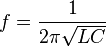
Capacitors and inductors are applied together in tuned circuits to select information in particular frequency bands. For example, radio receivers rely on variable capacitors to tune the station frequency. Speakers use passive analog crossovers, and analog equalizers use capacitors to select different audio bands.The resonant frequency f of a tuned circuit is a function of the inductance (L) and capacitance (C) in series, and is given by:
Sensing
-
Main article: capacitive sensing
-
Main article: Capacitive displacement sensor
Changing the dielectric:
- The effects of varying the characteristics of the dielectric can be used for sensing purposes. Capacitors with an exposed and porous dielectric can be used to measure humidity in air. Capacitors are used to accurately measure the fuel level in airplanes; as the fuel covers more of a pair of plates, the circuit capacitance increases.
- Capacitors with a flexible plate can be used to measure strain or pressure. Industrial pressure transmitters used for process control use pressure-sensing diaphragms, which form a capacitor plate of an oscillator circuit. Capacitors are used as the sensor in condenser microphones, where one plate is moved by air pressure, relative to the fixed position of the other plate. Some accelerometers use MEMS capacitors etched on a chip to measure the magnitude and direction of the acceleration vector. They are used to detect changes in acceleration, in tilt sensors, or to detect free fall, as sensors triggering airbag deployment, and in many other applications. Some fingerprint sensors use capacitors. Additionally, a user can adjust the pitch of a theremin musical instrument by moving their hand since this changes the effective capacitance between the user's hand and the antenna.
- Capacitive touch switches are now used on many consumer electronic products.
Oscillators
Further information: Hartley oscillator

Example of a simple oscillator that requires a capacitor to function
Hazards and safety
Capacitors may retain a charge long after power is removed from a circuit; this charge can cause dangerous or even potentially fatal shocks or damage connected equipment. For example, even a seemingly innocuous device such as a disposable camera flash unit powered by a 1.5 volt AA battery contains a capacitor which may be charged to over 300 volts. This is easily capable of delivering a shock. Service procedures for electronic devices usually include instructions to discharge large or high-voltage capacitors, for instance using a Brinkley stick. Capacitors may also have built-in discharge resistors to dissipate stored energy to a safe level within a few seconds after power is removed. High-voltage capacitors are stored with the terminals shorted, as protection from potentially dangerous voltages due to dielectric absorption.Some old, large oil-filled paper or plastic film capacitors contain polychlorinated biphenyls (PCBs). It is known that waste PCBs can leak into groundwater under landfills. Capacitors containing PCB were labelled as containing "Askarel" and several other trade names. PCB-filled paper capacitors are found in very old (pre-1975) fluorescent lamp ballasts, and other applications.
Capacitors may catastrophically fail when subjected to voltages or currents beyond their rating, or as they reach their normal end of life. Dielectric or metal interconnection failures may create arcing that vaporizes the dielectric fluid, resulting in case bulging, rupture, or even an explosion. Capacitors used in RF or sustained high-current applications can overheat, especially in the center of the capacitor rolls. Capacitors used within high-energy capacitor banks can violently explode when a short in one capacitor causes sudden dumping of energy stored in the rest of the bank into the failing unit. High voltage vacuum capacitors can generate soft X-rays even during normal operation. Proper containment, fusing, and preventive maintenance can help to minimize these hazards.
High-voltage capacitors can benefit from a pre-charge to limit in-rush currents at power-up of high voltage direct current (HVDC) circuits. This will extend the life of the component and may mitigate high-voltage hazards.
Inductors:
An inductor, also called a coil or reactor, is a passive two-terminal electrical component which resists changes in electric current passing through it. It consists of a conductor such as a wire, usually wound into a coil. When a current flows through it, energy is stored temporarily in a magnetic field in the coil. When the current flowing through an inductor changes, the time-varying magnetic field induces a voltage in the conductor, according to Faraday’s law of electromagnetic induction, which opposes the change in current that created it.
An inductor is characterized by its inductance, the ratio of the voltage to the rate of change of current, which has units of henries (H). Inductors have values that typically range from 1 µH (10−6H) to 1 H. Many inductors have a magnetic core made of iron or ferrite inside the coil, which serves to increase the magnetic field and thus the inductance. Along with capacitors and resistors, inductors are one of the three passive linear circuit elements that make up electric circuits. Inductors are widely used in alternating current (AC) electronic equipment, particularly in radio equipment. They are used to block the flow of AC current while allowing DC to pass; inductors designed for this purpose are called chokes. They are also used in electronic filters to separate signals of different frequencies, and in combination with capacitors to make tuned circuits, used to tune radio and TV receivers.
Inductance (L) results from the magnetic field around a current-carrying conductor; the electric current through the conductor creates a magnetic flux. Mathematically speaking, inductance is determined by how much magnetic flux φ through the circuit is created by a given current i[1][2][3][4]
 (1)
(1)

Constitutive equation
Any change in the current through an inductor creates a changing flux, inducing a voltage across the inductor. By Faraday's law of induction, the voltage induced by any change in magnetic flux through the circuit is[4]
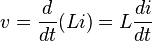 (2)
(2)
The dual of the inductor is the capacitor, which stores energy in an electric field rather than a magnetic field. Its current-voltage relation is obtained by exchanging current and voltage in the inductor equations and replacing L with the capacitance C.
Lenz's law
The polarity (direction) of the induced voltage is given by Lenz's law, which states that it will be such as to oppose the change in current. For example, if the current through an inductor is increasing, the induced voltage will be positive at the terminal through which the current enters and negative at the terminal through which it leaves. The energy from the external circuit necessary to overcome this potential "hill" is being stored in the magnetic field of the inductor; the inductor is said to be "charging" or "energizing". If the current is decreasing, the induced voltage will be negative at the terminal through which the current enters. Energy from the magnetic field is being returned to the circuit; the inductor is said to be "discharging".Ideal and real inductors
In circuit theory, inductors are idealized as obeying the mathematical relation (2) above precisely. An "ideal inductor" has inductance, but no resistance or capacitance, and does not dissipate or radiate energy. However real inductors have side effects which cause their behavior to depart from this simple model. They have resistance (due to the resistance of the wire and energy losses in core material), and parasitic capacitance (due to the electric field between the turns of wire which are at slightly different potentials). At high frequencies the capacitance begins to affect the inductor's behavior; at some frequency, real inductors behave as resonant circuits, becoming self-resonant. Above the resonant frequency the capacitive reactance becomes the dominant part of the impedance. At higher frequencies, resistive losses in the windings increase due to skin effect and proximity effect.Inductors with ferromagnetic cores have additional energy losses due to hysteresis and eddy currents in the core, which increase with frequency. At high currents, iron core inductors also show gradual departure from ideal behavior due to nonlinearity caused by magnetic saturation of the core. An inductor may radiate electromagnetic energy into surrounding space and circuits, and may absorb electromagnetic emissions from other circuits, causing electromagnetic interference (EMI). Real-world inductor applications may consider these parasitic parameters as important as the inductance.
Applications

Large 50 MVAR three-phase iron-core loading inductor at German utility substation

A ferrite "bead" choke, consisting of an encircling ferrite cylinder, removes electronic noise from a computer power cord.

Example of signal filtering. In this configuration, the inductor blocks AC current, while allowing DC current to pass.

Example of signal filtering. In this configuration, the inductor decouples DC current, while allowing AC current to pass.
An inductor connected to a capacitor forms a tuned circuit, which acts as a resonator for oscillating current. Tuned circuits are widely used in radio frequency equipment such as radio transmitters and receivers, as narrow bandpass filters to select a single frequency from a composite signal, and in electronic oscillators to generate sinusoidal signals.
Two (or more) inductors in proximity that have coupled magnetic flux (mutual inductance) form a transformer, which is a fundamental component of every electric utility power grid. The efficiency of a transformer may decrease as the frequency increases due to eddy currents in the core material and skin effect on the windings. The size of the core can be decreased at higher frequencies. For this reason, aircraft use 400 hertz alternating current rather than the usual 50 or 60 hertz, allowing a great saving in weight from the use of smaller transformers.[5]
Inductors are also employed in electrical transmission systems, where they are used to limit switching currents and fault currents. In this field, they are more commonly referred to as reactors.
Because inductors have complicated side effects (detailed below) which cause them to depart from ideal behavior, because they can radiate electromagnetic interference (EMI), and most of all because of their bulk which prevents them from being integrated on semiconductor chips, the use of inductors is declining in modern electronic devices, particularly compact portable devices. Real inductors are increasingly being replaced by active circuits such as the gyrator which can synthesize inductance using capacitors.
Inductor construction

A ferrite core inductor with two 47 mH windings.
Small inductors can be etched directly onto a printed circuit board by laying out the trace in a spiral pattern. Some such planar inductors use a planar core.
Small value inductors can also be built on integrated circuits using the same processes that are used to make transistors. Aluminium interconnect is typically used, laid out in a spiral coil pattern. However, the small dimensions limit the inductance, and it is far more common to use a circuit called a "gyrator" that uses a capacitor and active components to behave similarly to an inductor.
Types of inductor
Air core inductor
Resonant oscillation transformer from a spark gap transmitter. Coupling
can be adjusted by moving the top coil on the support rod. Shows high Q
construction with spaced turns of large diameter tubing.
Radio frequency inductor
Collection of RF inductors, showing techniques to reduce losses. The three top left and the ferrite loopstick or rod antenna,[6][7][8][9] bottom, have basket windings.
- Skin effect: The resistance of a wire to high frequency current is higher than its resistance to direct current because of skin effect. Radio frequency alternating current does not penetrate far into the body of a conductor but travels along its surface. Therefore, in a solid wire, most of the cross sectional area of the wire is not used to conduct the current, which is in a narrow annulus on the surface. This effect increases the resistance of the wire in the coil, which may already have a relatively high resistance due to its length and small diameter.
- Proximity effect: Another similar effect that also increases the resistance of the wire at high frequencies is proximity effect, which occurs in parallel wires that lie close to each other. The individual magnetic field of adjacent turns induces eddy currents in the wire of the coil, which causes the current in the conductor to be concentrated in a thin strip on the side near the adjacent wire. Like skin effect, this reduces the effective cross-sectional area of the wire conducting current, increasing its resistance.
High Q tank coil in a shortwave transmitter

Adjustable ferrite slug RF coil using lateral or wavewound winding and litz wire
- Dielectric losses: The high frequency electric field near the conductors in a tank coil can cause the motion of polar molecules in nearby insulating materials, dissipating energy as heat. So coils used for tuned circuits are often not wound on coil forms but are suspended in air, supported by narrow plastic or ceramic strips.
- Parasitic capacitance: The capacitance between individual wire turns of the coil, called parasitic capacitance, does not cause energy losses but can change the behavior of the coil. Each turn of the coil is at a slightly different potential, so the electric field between neighboring turns stores charge on the wire, so the coil acts as if it has a capacitor in parallel with it. At a high enough frequency this capacitance can resonate with the inductance of the coil forming a tuned circuit, causing the coil to become self-resonant.
- Basket-weave coils: To reduce proximity effect and parasitic capacitance, multilayer RF coils are wound in patterns in which successive turns are not parallel but crisscrossed at an angle; these are often called honeycomb or basket-weave coils.These are often wound on a vertical insulating supports with dowels or slots, with the wire weaving in and out through the slots; typically over one under one or over one under two. these are called basket weave coils. The form has an odd number of slots, so successive turns of the coil lie on opposite sides of the form, increasing separation.
- Spiderweb coils: Another construction technique with similar advantages is flat spiral coils.These are often wound on a flat insulating support with radial spokes or slots, with the wire weaving in and out through the slots; these are called spiderweb coils. The form has an odd number of slots, so successive turns of the spiral lie on opposite sides of the form, increasing separation.
- Litz wire: To reduce skin effect losses, some coils are wound with a special type of radio frequency wire called litz wire. Instead of a single solid conductor, litz wire consists of several smaller wire strands that carry the current. Unlike ordinary stranded wire, the strands are insulated from each other, to prevent skin effect from forcing the current to the surface, and are twisted or braided together. The twist pattern ensures that each wire strand spends the same amount of its length on the outside of the wire bundle, so skin effect distributes the current equally between the strands, resulting in a larger cross-sectional conduction area than an equivalent single wire.
Ferromagnetic core inductor

A variety of types of ferrite core inductors and transformers
- Core losses:
A time-varying current in a ferromagnetic inductor, which causes a
time-varying magnetic field in its core, causes energy losses in the
core material that are dissipated as heat, due to two processes:
- Eddy currents: From Faraday's law of induction, the changing magnetic field can induce circulating loops of electric current in the conductive metal core. The energy in these currents is dissipated as heat in the resistance of the core material. The amount of energy lost increases with the area inside the loop of current.
- Hysteresis: Changing or reversing the magnetic field in the core also causes losses due to the motion of the tiny magnetic domains it is composed of. The energy loss is proportional to the area of the hysteresis loop in the BH graph of the core material. Materials with low coercivity have narrow hysteresis loops and so low hysteresis losses.
- For both of these processes, the energy loss per cycle of alternating current is constant, so core losses increase linearly with frequency. Online core loss calculators[10] are available to calculate the energy loss. Using inputs such as input voltage, output voltage, output current, frequency, ambient temperature, and inductance these calculators can predict the losses of the inductors core and AC/DC based on the operating condition of the circuit being used.[11]
- Nonlinearity: If the current through a ferromagnetic core coil is high enough that the magnetic core saturates, the inductance will not remain constant but will change with the current through the device. This is called nonlinearity and results in distortion of the signal. For example, audio signals can suffer intermodulation distortion in saturated inductors. To prevent this, in linear circuits the current through iron core inductors must be limited below the saturation level. Some laminated cores have a narrow air gap in them for this purpose, and powdered iron cores have a distributed air gap. This allows higher levels of magnetic flux and thus higher currents through the inductor before it saturates.[12]
Laminated core inductor

Laminated iron core ballast inductor for a metal halide lamp
Ferrite-core inductor
For higher frequencies, inductors are made with cores of ferrite. Ferrite is a ceramic ferrimagnetic material that is nonconductive, so eddy currents cannot flow within it. The formulation of ferrite is xxFe2O4 where xx represents various metals. For inductor cores soft ferrites are used, which have low coercivity and thus low hysteresis losses. Another similar material is powdered iron cemented with a binder.Toroidal core inductor
Main article: Toroidal inductors and transformers

Toroidal inductor in the power supply of a wireless router
Choke
Main article: Choke (electronics)

An MF or HF radio choke for tenths of an ampere, and a ferrite bead VHF choke for several amperes.
Variable inductor


(left) Inductor with a threaded ferrite slug (visible at top) that can be turned to move it into or out of the coil. 4.2 cm high. (right) A variometer used in radio receivers in the 1920s

A "roller coil", an adjustable air-core RF inductor used in the tuned circuits
of radio transmitters. One of the contacts to the coil is made by the
small grooved wheel, which rides on the wire. Turning the shaft rotates
the coil, moving the contact wheel up or down the coil, allowing more or
fewer turns of the coil into the circuit, to change the inductance.
Air core inductors can use sliding contacts or multiple taps to increase or decrease the number of turns included in the circuit, to change the inductance. A type much used in the past but mostly obsolete today has a spring contact that can slide along the bare surface of the windings. The disadvantage of this type is that the contact usually short-circuits one or more turns. These turns act like a single-turn short-circuited transformer secondary winding; the large currents induced in them cause power losses.
A type of continuously variable air core inductor is the variometer. This consists of two coils with the same number of turns connected in series, one inside the other. The inner coil is mounted on a shaft so its axis can be turned with respect to the outer coil. When the two coils' axes are collinear, with the magnetic fields pointing in the same direction, the fields add and the inductance is maximum. When the inner coil is turned so its axis is at an angle with the outer, the mutual inductance between them is smaller so the total inductance is less. When the inner coil is turned 180° so the coils are collinear with their magnetic fields opposing, the two fields cancel each other and the inductance is very small. This type has the advantage that it is continuously variable over a wide range. It is used in antenna tuners and matching circuits to match low frequency transmitters to their antennas.
Another method to control the inductance without any moving parts requires an additional DC current bias winding which controls the permeability of an easily saturable core material. See Magnetic amplifier.
Circuit theory
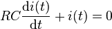
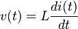
The effect of an inductor in a circuit is to oppose changes in current through it by developing a voltage across it proportional to the rate of change of the current. An ideal inductor would offer no resistance to a constant direct current; however, only superconducting inductors have truly zero electrical resistance.The relationship between the time-varying voltage v(t) across an inductor with inductance L and the time-varying current i(t) passing through it is described by the differential equation:

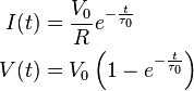
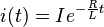
If an inductor is connected to a direct current source with value I via a resistance R, and then the current source is short-circuited, the differential relationship above shows that the current through the inductor will discharge with an exponential decay:
Reactance
The ratio of the peak voltage to the peak current in an inductor energised from a sinusoidal source is called the reactance and is denoted XL. The suffix is to distinguish inductive reactance from capacitive reactance due to capacitance.

Laplace circuit analysis (s-domain)
When using the Laplace transform in circuit analysis, the impedance of an ideal inductor with no initial current is represented in the s domain by:
 is the inductance, and
 is the complex frequency.
- adding a voltage source in series with the inductor, having the value:

- is the inductance, and
 is the initial current in the inductor.
- or by adding a current source in parallel with the inductor, having the value:

- is the initial current in the inductor.
- is the complex frequency.
Inductor networks
Main article: Series and parallel circuits
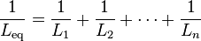
Inductors in a parallel configuration each have the same potential difference (voltage). To find their total equivalent inductance (Leq):


Stored energy
Neglecting losses, the energy (measured in joules, in SI) stored by an inductor is equal to the amount of work required to establish the current through the inductor, and therefore the magnetic field. This is given by:
This relationship is only valid for linear (non-saturated) regions of the magnetic flux linkage and current relationship. In general if one decides to find the energy stored in a LTI inductor that has initial current in a specific time between
 and
and  can use this:
Q factor
An ideal inductor would have no resistance or energy losses. However, real inductors have winding resistance from the metal wire forming the coils. Since the winding resistance appears as a resistance in series with the inductor, it is often called the series resistance. The inductor's series resistance converts electric current through the coils into heat, thus causing a loss of inductive quality. The quality factor (or Q) of an inductor is the ratio of its inductive reactance to its resistance at a given frequency, and is a measure of its efficiency. The higher the Q factor of the inductor, the closer it approaches the behavior of an ideal, lossless, inductor. High Q inductors are used with capacitors to make resonant circuits in radio transmitters and receivers. The higher the Q is, the narrower the bandwidth of the resonant circuit.The Q factor of an inductor can be found through the following formula, where L is the inductance, R is the inductor's effective series resistance, ω is the radian operating frequency, and the product ωL is the inductive reactance:

Qualitatively at low frequencies and within limits, increasing the number of turns N improves Q because L varies as N2 while R varies linearly with N. Similarly, increasing the radius r of an inductor improves Q because L varies as r2 while R varies linearly with r. So high Q air core inductors often have large diameters and many turns. Both of those examples assume the diameter of the wire stays the same, so both examples use proportionally more wire (copper). If the total mass of wire is held constant, then there would be no advantage to increasing the number of turns or the radius of the turns because the wire would have to be proportionally thinner.
Using a high permeability ferromagnetic core can greatly increase the inductance for the same amount of copper, so the core can also increase the Q. Cores however also introduce losses that increase with frequency. The core material is chosen for best results for the frequency band. At VHF or higher frequencies an air core is likely to be used.
Inductors wound around a ferromagnetic core may saturate at high currents, causing a dramatic decrease in inductance (and Q). This phenomenon can be avoided by using a (physically larger) air core inductor. A well designed air core inductor may have a Q of several hundred.
Inductance formulae
The table below lists some common simplified formulas for calculating the approximate inductance of several inductor constructions.| Construction | Formula | Notes |
|---|---|---|
| Cylindrical air-core coil[14] | 
|
The exact calculation of K is complex. K is approximately unity for a coil which is much longer than its diameter and is tightly wound using small gauge wire (so that it approximates a current sheet).[15] |
| Straight wire conductor[16] | ![L = \frac{\mu_0}{2\pi} \left(
l \ln\left[\frac{1}{c}\left(l + \sqrt{l^2 + c^2}\right)\right] - \sqrt{l^2 + c^2} +
c + \frac{l}{4 + c \sqrt{\frac{2}{\rho}\omega\mu}}
\right)](http://upload.wikimedia.org/math/e/f/a/efa2d7d584be0f98d7f29ea5f27764a5.png)
|
Exact if ω = 0 or ω = ∞ |
![L = \frac{1}{5} l \left[\ln\left(\frac{4l}{d}\right) - 1\right]](http://upload.wikimedia.org/math/6/e/a/6eae9f27f452930f27961b76fdef67f9.png)
|
|
|
![L = \frac{1}{5} l \left[\ln\left(\frac{4l}{d}\right) - \frac{3}{4}\right]](http://upload.wikimedia.org/math/2/f/9/2f9d2129afc2623a650fc45b5271a686.png)
|
|
|
| Short air-core cylindrical coil[21] | 
|
|
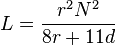
| Multilayer air-core coil[citation needed] | 
|
|
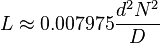
| Flat spiral air-core coil[22][citation needed] | 
|
|
|
accurate to within 5 percent for d > 0.2 r.[23] | |
| Toroidal core (circular cross-section)[24] | 
|
|
|
approximation when d < 0.1 D | |
| Toroidal core (rectangular cross-section)[23] | 
|
 × 10−7 H/m
No comments:
Post a Comment